(Last updated: June 8 2020)
I was working with a team this week, that created some architecture diagrams in the PlantUML tool. The output images looked really neat, and they were super easy to extend and adapt. I wanted to dive into this for myself, and share with all of you what I learned.
So let’s start with what UML is: UML or Unified Modeling Language is a standardized modeling language to represent software architecture. It can be used to represent a couple of things, from a class diagram to a sequence diagram.
PlantUML is a tool that allows you to create and manage UML diagrams in code, rather than on a whiteboard or in Visio. You define your diagrams in code, and then compile or transform them into a nice PNG image.
Now, why am I so interested in this you might ask? I typically use Visio to create my architecture diagrams. Although you can achieve a lot in Visio, and create nice diagrams, the problem always arises when you need to add a component to your architecture. It takes a while to re-order your diagram and integrate a new component in your diagram. Which PlantUML actually manages for you: you just type up your diagram and the relationships in it, and it will manage a nice visualization. Plus, that code can be source controlled, so you have a full history of your changes.
With that, let’s dive in the installation and let’s create a first diagram together.
Getting started with PlantUML on Ubuntu
First things first, we need a Java Runtime Environment and graphviz. To get that installed:
sudo apt-get update
sudo apt-get install default-jre graphviz -y
With that done, we need to download the plantuml jar file, which you can find here. I moved my file to /usr/bin, but you don’t have to.
wget http://sourceforge.net/projects/plantuml/files/plantuml.jar/download -O plantuml.jar
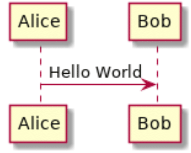
sudo mv plantuml.jar /usr/binOnce we have the jar file, we can try out a small ‘hello world’ UML diagram. You can install a PlantUML plugin into VScode, to even get code highlighting. Make sure to use the wsd file name extension if you plan to use VScode with the plugin.
@startuml
Alice -> Bob: Hello World
@enduml
Let’s save this file (I called it helloworld.wsd) – and try to transform it into PNG:
java -jar /usr/bin/plantuml.jar helloworld.wsdThis leads to a file called helloworld.png being created, which will look like this:
To make things easier, you could also make an alias to refer to plantuml without typing the full java syntax. Do this by adding the following line to your profile (either .bashrc or .zshrc, based on which shell you use):
alias plantuml='java -jar /usr/bin/plantuml.jar'Reload your profile ( source ~/.zshrc ) and then you can create PlantUML diagram using:
plantuml helloworld.wsdCreating a flow diagram
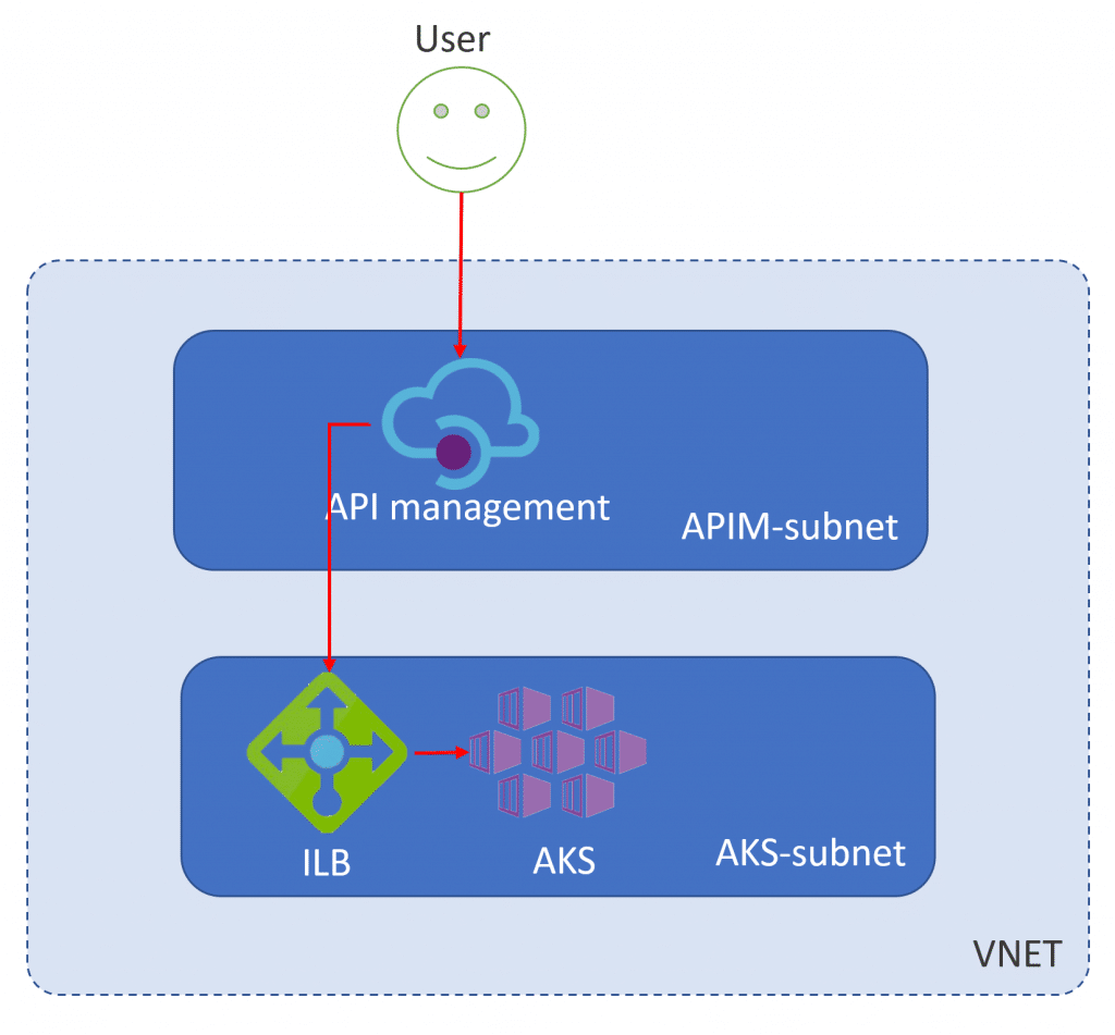
I have got a blog post in draft, for which I created the following architecture diagram. Why don’t we try to convert this into a PlantUML diagram?
Let’s build our deployment diagram together, step by step. We’ll be using this documentation article to build out our diagram.
So, step 1 is creating a square/rectangle for our VNET and the subnets in it. I decided to use the frame object to represent my VNET and the subnets in it. The following code will generate the following output:
@startuml Api Management in front of AKS

title High Level Architecture - API Management in front of AKS

frame VNET{
    frame APIM-subnet{

    }
    frame AKS-subnet{

    }
}
@enduml
Afterwards, we’ll add objects for API Management, the ILB and our AKS cluster. We’ll use nodes to represent them. Again, the following code will compile in the following PNG:
@startuml Api Management in front of AKS

title High Level Architecture - API Management in front of AKS

frame VNET{
    frame APIM-subnet{
        node "API Management"
    }
    frame AKS-subnet{
        node "ILB"
        node "AKS Cluster"
    }
}
@enduml
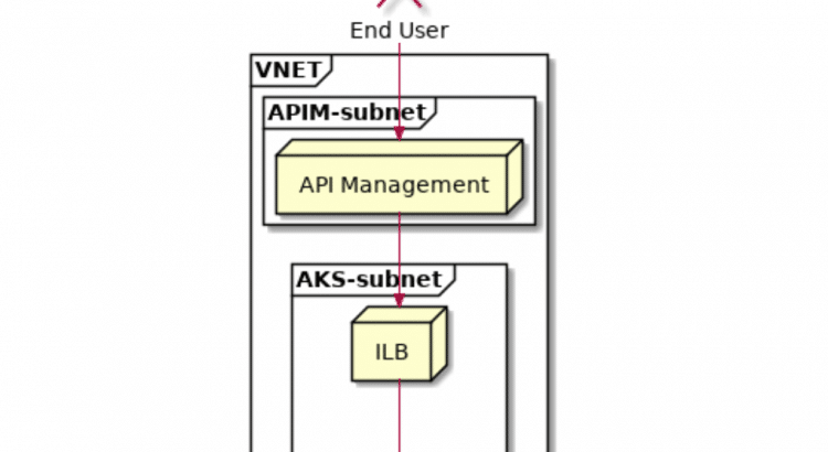
Now, we need to add a user to the mix. This can be done by the actor object. Again, the following code compiles into the following design:
@startuml Api Management in front of AKS

title High Level Architecture - API Management in front of AKS

actor "End User"

frame VNET{
    frame APIM-subnet{
        node "API Management"
    }
    frame AKS-subnet{
        node "ILB"
        node "AKS Cluster"
    }
}
@enduml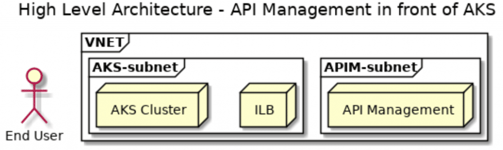
I don’t know if you have been paying attention so far, but PlantUML does weird things with ordering things left to right or right to left. Within the VNET frame, there are two frame, APIM and AKS. Those are ordered right to left (APIM before AKS). The holds true for the ILB and AKS cluster in the AKS-subnet. But our end-user is then positioned left-to-right to our VNET. (all of this based on reading the document top to bottom). Not that I care much about that order, but I wonder what is going to happen once we start drawing connections, which we’ll do now.
PlantUML has a lot of different ways to represent arrows. I picked one design to represent all my flows, which is -->>. We’ll add these arrows to the bottom of our file. The following code will create the following output:
@startuml Api Management in front of AKS

title High Level Architecture - API Management in front of AKS

actor "End User" as eu

frame VNET{
    frame APIM-subnet{
        node "API Management" as apim
    }
    frame AKS-subnet{
        node "ILB" as ilb
        node "AKS Cluster" as aks
    }
}

eu -->> apim
apim -->> ilb
ilb -->> aks
@enduml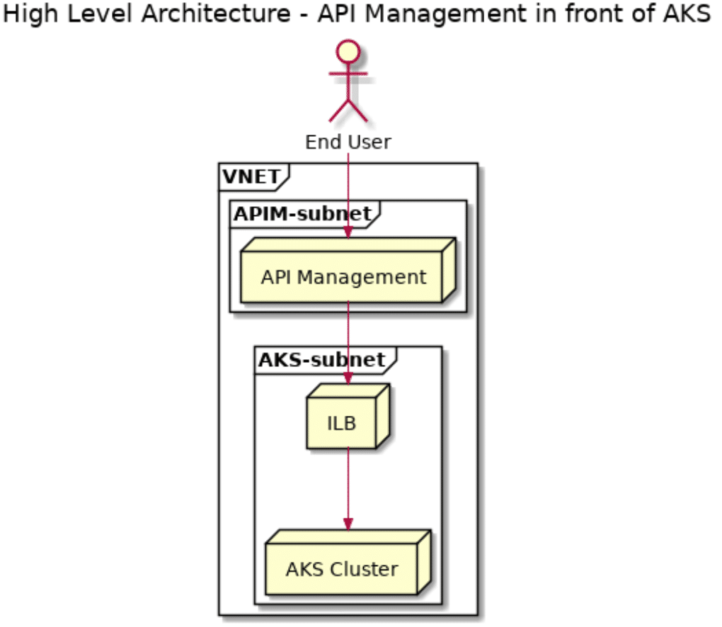
Looking at the output diagram, vs the input diagram, they now look pretty similar. Both have their benefits, one looks prettier in marketing-architectures, the second one can be source controlled and is a lot more easily extended.
Conclusion
Working with a new team introduced my to PlantUML, and I can certainly see the value in the tool. Having architectures checked into source control, and having them as code is very valuable. Source control creates some historical visibility in changes, and having them as code makes them a lot more easy to extend. Not the best tool for marketing-architectures, but certainly a good to to represent a detailed architecture.
I am happy to have a new tool in my tool belt. I hope you are too.
And with that, I hope to finish the APIM in front of AKS blog post over the weekend and publish that next week. Coming soon!